MIT 2.007 Robot


In the spring of my sophomore semester at MIT, I took a capstone mechanical engineering class: Design & Manufacturing I (2.007). In this class, students are challenged to design and fabricate robots to complete a variety of different tasks, and ultimately compete against their peers to determine which robot is the best! The final tournament is structured in a traditional bracket style; students/robots go head-to-head, and the person that earns more points moves on to the next round until only a final victor remains. Each year, a competition board is designed by the instructors with a number of different tasks that can be completed to earn different amounts of points. Students must design mechanisms to complete as many tasks as possible in the allotted competition time, and the goal is to earn more points than your opponent. My robot made it to the top 16 robots in the competition out of over 100 participants!
Course Overview
-
I designed my entire robot in Fusion 360, accounting for every screw and joint that was ultimately used in the final assembly of the actual robot. This made the manufacturing process far less complex, as I knew all of the dimensions of my robot and foresaw which components might be difficult to assemble.
-
Most of my robot was fabricated using the water jet. I designed my robot in CAD to be easily produced using multiple sheets of sheet metal on the water jet. The main parts of the drive-base as well as the lifting mechanism was cut on the water jet.
-
The lathe was an instrumental tool in the fabrication process of my robot. I spent hours working on the lathe, making axels, shafts, and other small parts for my robot.
-
I also learned how to use the milling machine in order to machine very precisely dimensioned parts.
-
The wheel hubs of my robot were 3D printed, as I wanted them to have very specific dimensions and a custom joint between the wheel hub and its axel.
-
To quickly prototype components of my robot, I used the laser cutter to cut acrylic or plywood to test the rough sizing of certain pieces before cutting those pieces on the water jet.
Skills Used
The Gameboard
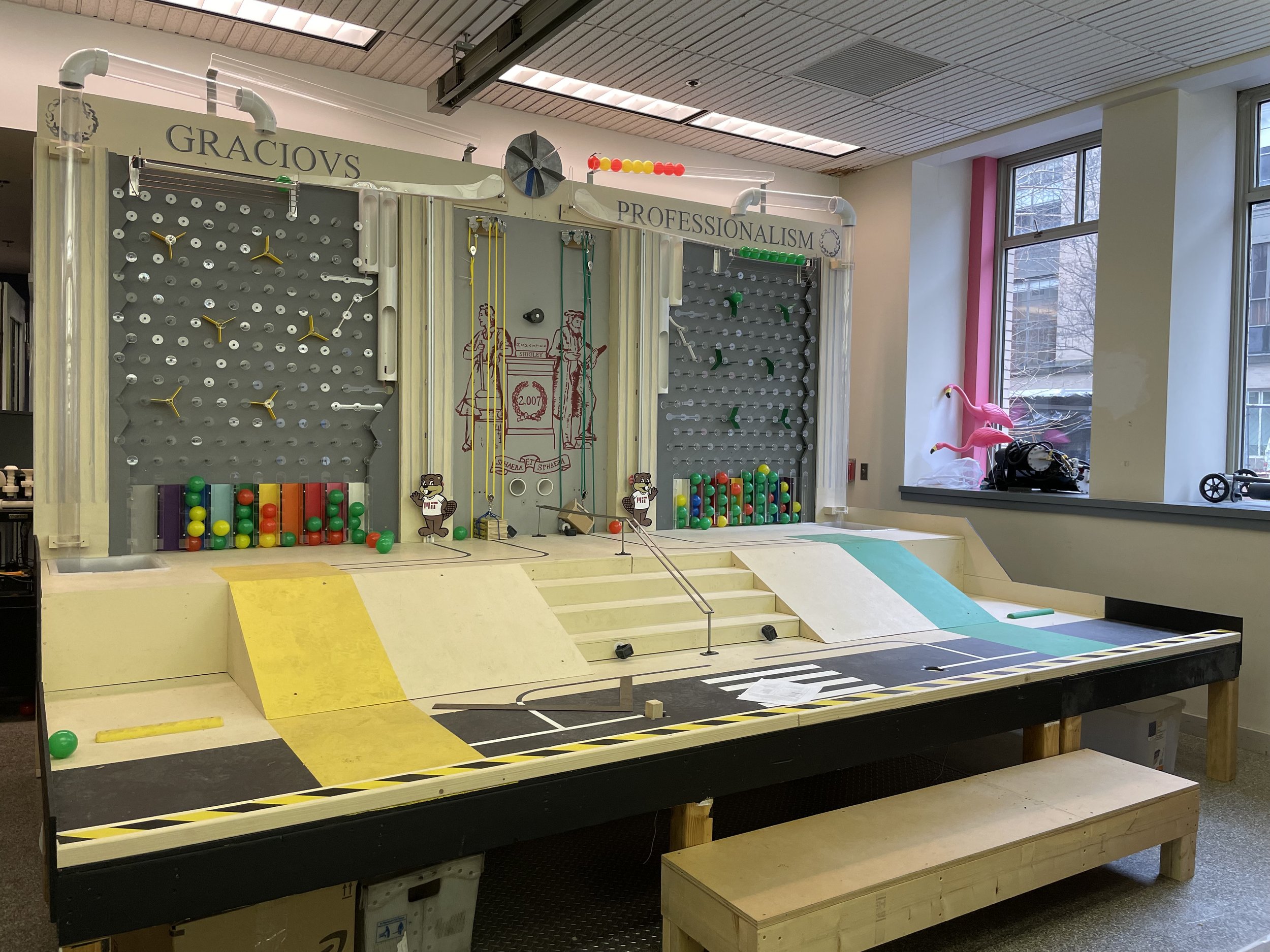
The gameboard has a variety of different tasks that can be completed by the student. Tasks include pulling a streetlamp onto your side, pressing buttons at varying heights, lifting a beaver to a specific height, pulling a brass rat a certain distance, pushing a square peg into a hole, collecting balls that are released onto the gameboard, climbing up an inclined ramp, and many more. The student must determine which tasks they wish to complete, what mechanisms they will need to build to complete those tasks, as well as design and build those mechanisms.
In addition, the student’s robot cannot exceed 12 pounds, and must fit within a 12’’x12’’x16’’ box.
CAD Overview


Using CAD, I was able to design my robot to the exact specifications and dimensions that the contest allowed. This also made the fabrication process much easier, as I could use the water jet to perfectly cut the components of my robot. This is a piece of the drive-base fresh off of the water jet!
The robots had to fit within a 12’’ x 12’’ x 16’’ box, and since I designed my robot in CAD, I was able to ensure that my robot perfectly fit within this size constraint.
Thanks to the CAD model of my robot, everything fit together as expected and the robot fit inside the starting box.
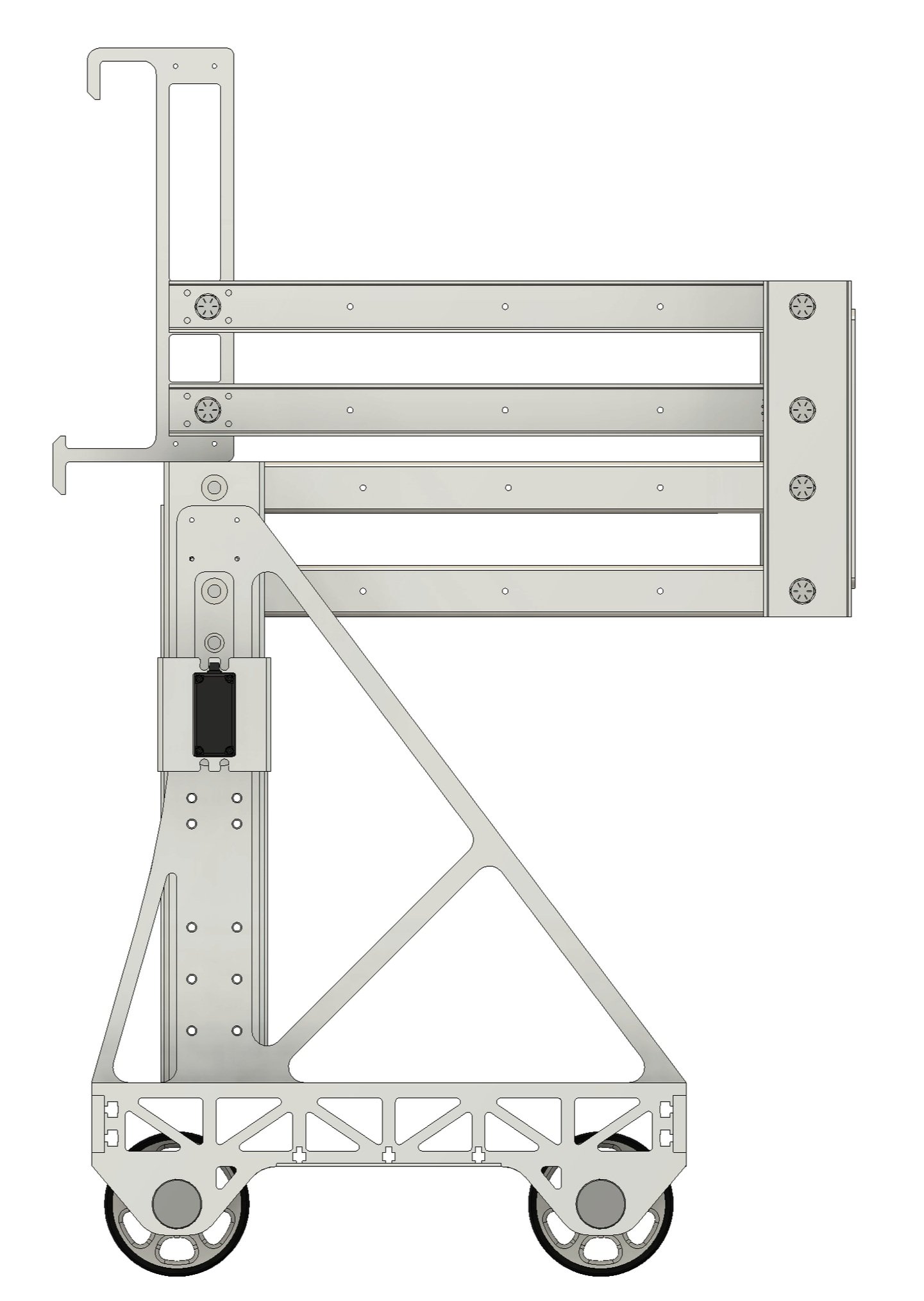
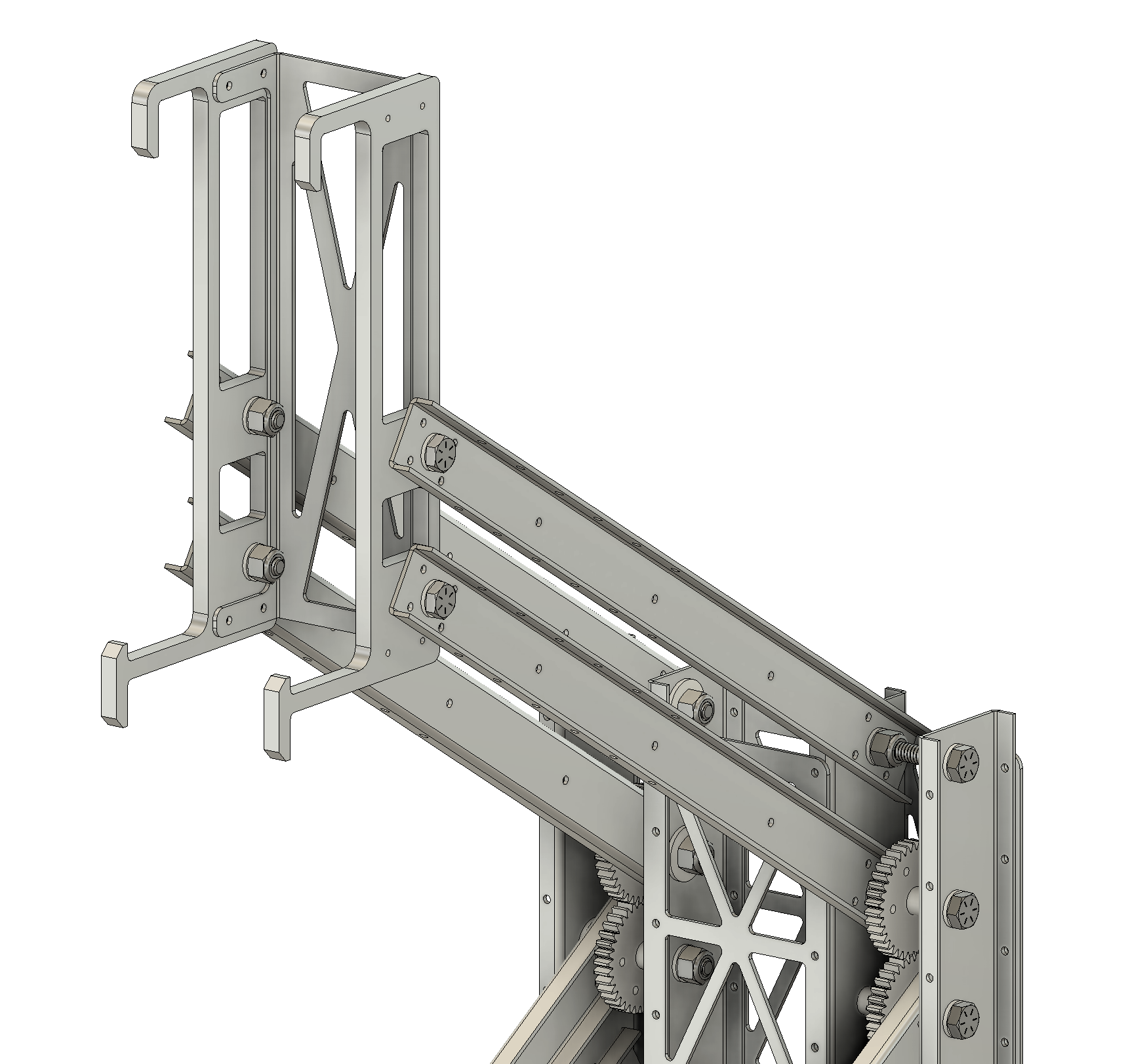
Lifting Mechanism (Reverse-Double-Four Bar)
As mentioned earlier, many of the tasks on the final gameboard require the robot to be able to push, pull, and/or lift some sort of object. This is where the versatility of a robust lifting mechanism comes into play; by building a mechanism that can move an end-effector vertically 40 inches, my robot was able to complete different tasks that were each positioned at various heights.
This is the first trial run of the reverse double four bar. Needless to say, it underwent a lot of revisions and fine-tuning, but this was the first successful lift!
These images show the gearing of the reverse-double-four bar. A torqued-up motor spins one of the four linkages, and due to the constraints of the entire linkage, the entire arm lifts vertically. Since the arms are all of equal length, there is theoretically zero horizontal movement in the lifting mechanism!
End-Effector
Due to the variety of different tasks the robot must complete, the design and versatility of the end-effector is extremely important. This end-effector can push, pull, drag, and hook on to different objects. Since it is being vertically moved by the reverse-double-four bar, we can control the height of the end-effector very precisely.
Drive Base
With all of these mechanisms in place, the final piece to this puzzle is the drive-base. Needless to say, the robot is nothing unless it can transport itself to the locations it needs to go to. I implemented a standard 4 wheel drive system, using a remote control to precisely move and steer the robot.
The Actual Competition!
To see my top 32 round, start watching the video at 1 hour, 7 minutes, and 47 seconds.
To see my top 16 round (where I get eliminated), start watching the video at 2 hours, 14 minutes, and 1 second.
What I Would Change
After designing and building my robot, competing in the competition, and having some time to reflect, there are a couple things I would change if I were to take this class again and redesign my robot.
-
Due to the way I designed my drive-base, to prevent having the wheels cantilevered, I placed them on the inside of the drive-base frame. This is not great for mobility and steering, and resulted in the robot “jumping” every time it tried to turn. If I were to redesign my robot, I would place my wheels on the outside of the drive-base and allow them to be cantilevered. This is how cars position and support their wheels, so I’m not sure why I felt the need to do things differently.
-
I spent a lot of time designing my robot to be just under the maximum specifications allowed in the competition. While it is certainly important to design within the set constraints, in hindsight, I realize that I did not need this additional size and weight, and if anything, it resulted in my robot being slower and less agile than it could have been, with little to no benefit. Next time, I would design my robot to be as small as it could be without compromising functionality.
-
Given that this entire robot was conceived, designed, prototyped, and built in one semester while I was taking four other technical classes, I couldn’t devote as much time as I would have liked to practice driving my robot once I finished building it. I believe this extra practice and familiarity with how my robot behaves could have saved me a lot of time during the competition and could even result in me scoring more points because I would have time to do one or two additional tasks.